Arduino Tutorial Project
|
|
Members: Minso Lim & Matthew Pinto
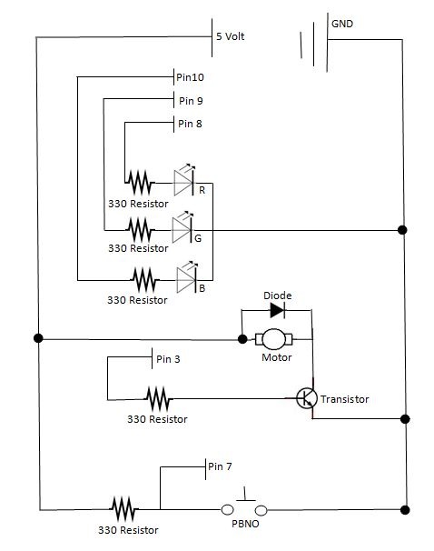
Arduino Schematics:
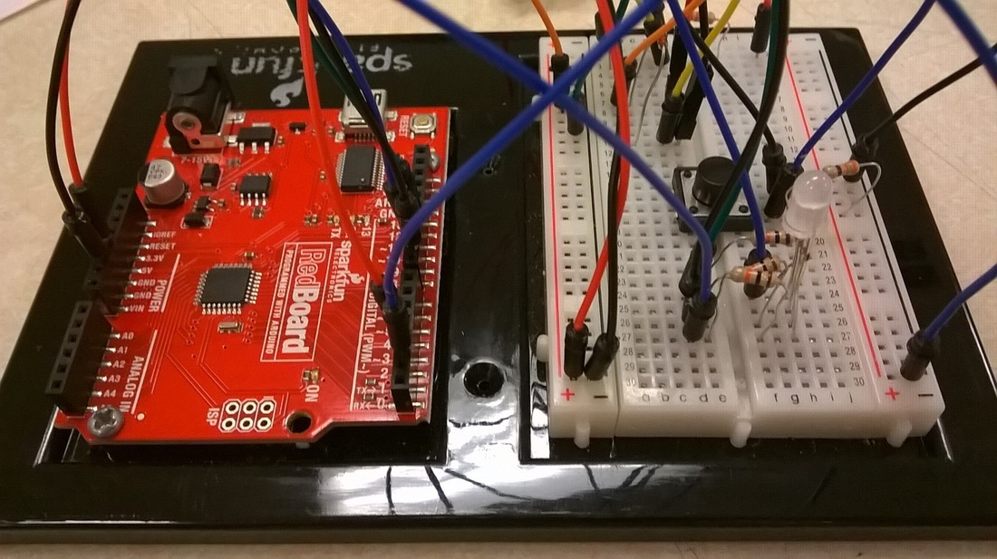
1. Put pin 9 into D27
2. Put pin 10 intoD 26
3. Put pin 11 into D25
4. Put pin 2 to H,18
5. Put pin 3 into I,2
6. Put ground pin into the negative hole 30A
7. Put 5V pin into positive hole near 30A
8. Place wire on A7 to the postive spot next to it
9. Place wire on f24 to negative near negative 30
10. Put wire on H 17 to negative hole
11. Place RGB LED onto holes H27, H26, H25, H24
12. place resistor on E27, E 26, and E24 to f,27 F26, F24
13. Place motor pins on E11 and E7
14. Place wire on D11, to D3
15. Place resistor on I18 to corresponding positive hole
16. Place push button on E19 and F19.
Arduino Schematics:
1. Put pin 9 into D27
2. Put pin 10 intoD 26
3. Put pin 11 into D25
4. Put pin 2 to H,18
5. Put pin 3 into I,2
6. Put ground pin into the negative hole 30A
7. Put 5V pin into positive hole near 30A
8. Place wire on A7 to the postive spot next to it
9. Place wire on f24 to negative near negative 30
10. Put wire on H 17 to negative hole
11. Place RGB LED onto holes H27, H26, H25, H24
12. place resistor on E27, E 26, and E24 to f,27 F26, F24
13. Place motor pins on E11 and E7
14. Place wire on D11, to D3
15. Place resistor on I18 to corresponding positive hole
16. Place push button on E19 and F19.
Code
//These are our constants
const int Red = 9;
const int Green = 10;
const int Blue =11;
const int POT =A0;
const int PBNO = 2;
int ButtonState = 0;
int motorPin =3;
void setup()
{
pinMode(Red, OUTPUT);// all pins are now outputs meaning they are the ones that will transmit the message
pinMode(Green,OUTPUT);
pinMode(Blue, OUTPUT);
pinMode (motorPin, OUTPUT);
pinMode(POT, INPUT);// both of these are inputs
pinMode (PBNO, INPUT);
}
void loop()
{
ButtonState = digitalRead(PBNO);// if the button is pressed the motor will start
if (ButtonState == HIGH) {
digitalWrite(motorPin, HIGH);
}
else {
digitalWrite(motorPin, LOW); // if not pressed motor remains off
}
{digitalWrite(motorPin, HIGH);
delay(1000);
digitalWrite (motorPin, LOW); //
delay (1000);
}
{
//Red
analogWrite(Red,255);
analogWrite(Green,0);
analogWrite(Blue,0);
delay (1000);
//Oranage
analogWrite(Red,255);
analogWrite(Green,127);
analogWrite(Blue,0);
delay (1000);
//Yellow
analogWrite(Red,255);
analogWrite(Green,255);
analogWrite(Blue,0);
delay (1000);
//Green Yellow
analogWrite(Red,127);
analogWrite(Green,255);
analogWrite(Blue,0);
delay (1000);
//Green
analogWrite(Red,0);
analogWrite(Green,255);
analogWrite(Blue,0);
delay (1000);
//Green Cyan
analogWrite(Red,0);
analogWrite(Green,255);
analogWrite(Blue,127);
delay (1000);
//Cyan
analogWrite(Red,0);
analogWrite(Green,255);
analogWrite(Blue,255);
delay (1000);
//Blue Cyan
analogWrite(Red,0);
analogWrite(Green,127);
analogWrite(Blue,255);
delay (1000);
//Blue
analogWrite(Red,0);
analogWrite(Green,0);
analogWrite(Blue,255);
delay (1000);
//Blue Magenta
analogWrite(Red,127);
analogWrite(Green,0);
analogWrite(Blue,255);
delay (1000);
//Magenta
analogWrite(Red,255);
analogWrite(Green,0);
analogWrite(Blue,255);
delay (1000);
//Red Magenta
analogWrite(Red,255);
analogWrite(Green,0);
analogWrite(Blue,127);
delay (1000);
}
}
Trouble shooting Guide
If you are having trouble understanding the code look in the comments
Make sure that all wires are in the correct spot
make sure you use transistor and not a temperature sensor they look very similar
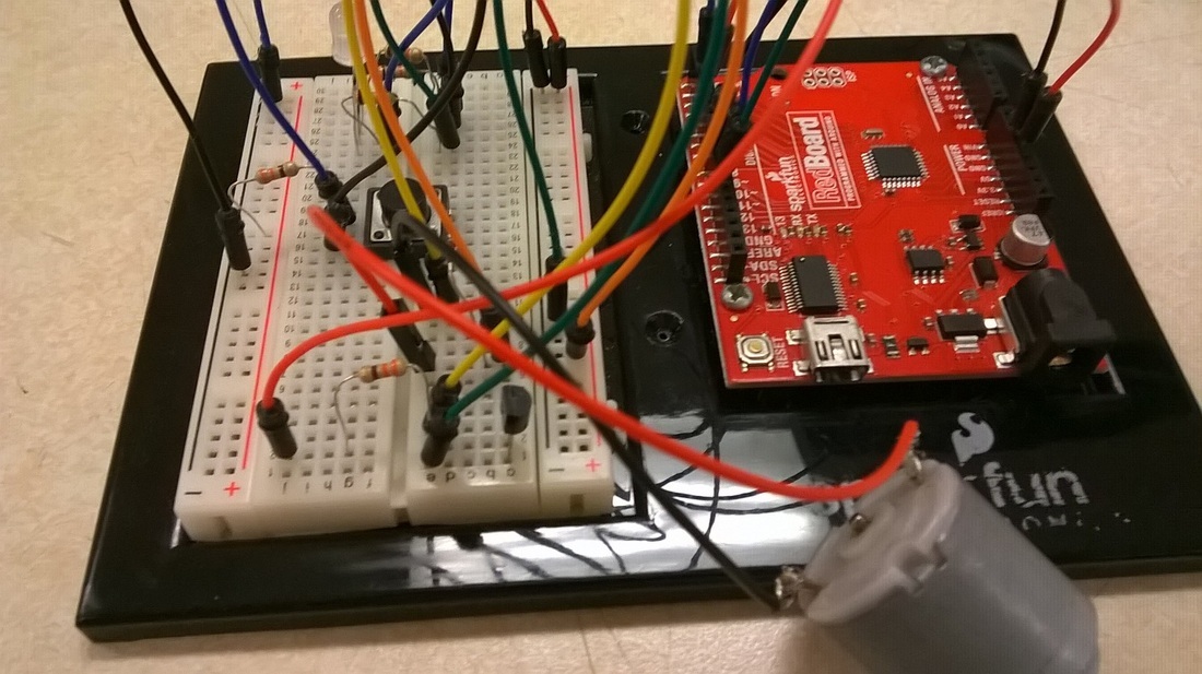
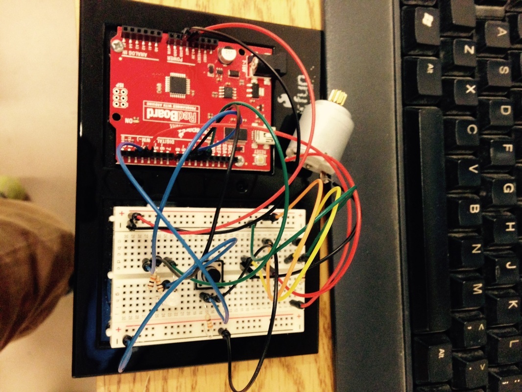
Use the pictures as a reference they are very helpful.
Make sure that all wires are in the correct spot
make sure you use transistor and not a temperature sensor they look very similar
Use the pictures as a reference they are very helpful.
All code created by Matthew and Minso, no third party sources
